


- >displacement sensor
- >osmolometer
- >strain gauge
- >ultrasonic sensor
- >hydraulic ceramics static level
- >tipping bucket rain gauge
- >inclinometer
- >acquisition device
- >audible and visual alarm
- >acceleration sensor
- >GNSS
- >water level gauge
- >fixed inclinometer
- >magnetostrictive static level
- >crystalline silicon static level
- >pull wire displacement sensor
- >video displacement sensor
- >laser ranging sensor
- >Vibrating string pore water pressure gauge
- >Vibrating string anchor cable dynamometer
- >Vibrating string earth pressure gauge
- >Vibrating wire type steel bar meter
- >Vibrating wire displacement sensor
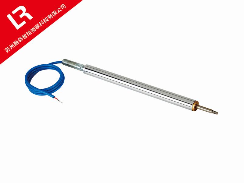
(1)Product Overview:The vibrating wire displacement meter is suitable for long-term measurement of the opening and closing degree (deformation) of expansion joints in hydraulic structures or other concrete buildings. It can also be used to measure the displacement, settlement, strain, and slip of structures such as earth dams, embankments, and slopes. Temperature sensors can be installed to synchronously measure the temperature of buried points.
(2)Basic product parameters:
① Structure:The vibrating string soil displacement meter consists of displacement transmission rod, transmission spring, steel string, electromagnetic coil, steel string bracket, waterproof sleeve, inner and outer protective sleeves of the guide ring, connecting rods at both ends, and universal joints.
② Main technical parameters:
Product model:RL-700
Specifications:50 100
Measurement range (mm):0~50 0~100
Resolution(%F.S):≤0.05%F.S
Comprehensive error(%F.S):≤1.0%/F.S
Temperature measurement accuracy(℃)Optional selection:±0.5℃
③Working principle:The grouting anchor bolt of the displacement meter is firmly connected to the rock mass. When the rock mass undergoes displacement along the axis of the borehole, the anchor bolt drives the transmission rod to extend to the reference end of the borehole, causing the elongation measuring instrument located at the reference end to also change accordingly with the displacement. With the movement of the anchor bolt, the elongation relative to the reference end can be measured. If a temperature sensor is installed, it can simultaneously measure the temperature value of the buried point.
④Calculation formula:
L=K(fo2-fi2 ) Note: Frequency modulus F=f2×10-3
In the formula:
L:Displacement, in millimeters
K:Calibration coefficient of displacement meter, unit: mm/Hz2
fo:Initial frequency reading (reference value) of the instrument when unloaded, in Hz
fi:The measured frequency reading (measured value) when the instrument displacement changes, in Hz
⑤Product embedding and installation:
External connection:
Measure the length of the stainless steel measuring rod according to the number of points and the design of each point. Connect the measuring rod with screws (dipped in glue), and screw a small connecting nut (10x30, usually already connected before leaving the factory) on the top of the measuring rod. (The length of the measuring rod needs to be separately configured according to the actual needs on site, and it is not directly configured at the factory).
Cover the measuring rod with an outer protective tube and connect the outer protective tube to a length smaller than 20-25cm of the measuring rod using outer protective tube joints (dipped in glue). Then, seal the joint (with an O-ring inside, the front anchor head, measuring rod, and outer protective tube have all been connected before leaving the factory) from the bottom of the measuring rod and connect it to the bottom of the outer protective tube (dipped in glue); Finally, put a flexible nut and a protective tube joint (glued) on the upper end of the outer protective tube.
Insert the top of the measuring rod (with a small nut joint) into the positioning seat through the joint hole on the bottom of the positioning seat, and tighten the positioning screw (M10) from the hole where the sensor is placed on the upper end of the positioning seat. The positioning screw should be tightened with the small connecting nut on the measuring rod (if it has been assembled before leaving the factory, this step can be omitted); Then attach the flexible nut on the outer protective tube and the protective tube joint (with adhesive).
Connect the measuring rods and protective tubes of the design quantity according to the above three steps. All connection parts should be firm enough not to fall off, and all tubes should be reliably positioned and tied into a bundle. Number the corresponding position of each measuring rod.
Unscrew the head screws on the grouting bubble face and exhaust hole, insert them into the grouting pipe and exhaust pipe. If grouting is done from the outside, there is no need to unscrew the head screws.
Place the grouting pipe and exhaust pipe together with the tied measuring rod and protective cover into the hole, and be careful not to damage the outer protective pipe when placing them.
⑥Grouting:
After the installation of the measuring rod is completed, fix the positioning flange with expansion bolts and start grouting. Inject grout according to the corresponding procedure to a certain height, and install each point in each soil layer required for construction. (Each soil layer must be separated by sand or soil)
⑦Installation and debugging of sensors:
After the mortar injected into the hole has basically solidified, first remove the positioning screw connected to the measuring rod in the installation hole of the positioning seat instrument, and then screw the thread at the top of the sensor displacement rod into the small connecting nut (dipped in glue). While tightening, use a frequency reading instrument to measure the reading of the sensor until the reading of the frequency reading instrument changes. Repeat this process until the remaining instruments are installed, and record the corresponding rod number for each sensor.
Tighten the protective cover and positioning seat securely, and insert the inner positioning plate (with a groove on the outer circle) from the upper end of the protective cover. The adjustment heads on the sensor should be threaded out of the inner positioning plate one by one, and the inner positioning plate should be fastened with fastening screws.
Use a special wrench to turn the adjustment cap on the adjustment head and make a pre adjustment for the initial installation value of the sensor. The pre adjustment method should be determined based on the development direction of the anchor head at the end of the measuring rod in the hole.
After pre adjusting the initial frequency values of all sensors, use a pressure plate to press the adjustment cap tightly until there is no gap.
Connect the measurement cable of the sensor reliably to the external output cable, record the color of the output cable core and the sensor number, so as to distinguish the depth of the sensor measurement point in future measurements.
Screw on the cover plate at the port of the protective cover and tighten the cable connector to ensure dust and anti-seepage measures are taken.
⑧Protect:
Fix the external output cable and provide protection. It is best to install a reliable protective device on the displacement meter (as long as the displacement meter is not damaged during future measurement), and the displacement meter can be put into use.
⑨Other:
After the installation and positioning of the displacement meter, the initial value of the instrument should be measured in a timely manner, and records should be made and archived according to the instrument number and design number. The lead out cable of the instrument should be strictly protected.